Gaming Controller for a Virtual Robot Vehicle
At the start of the pandemic, I had enrolled in a Mechanical Systems Laboratory course which focused on experiments in linear systems, including op-amp circuits, vibrations, and control systems. The main project in this class emphasized demonstrating that mathematical models can be useful tools for the analysis and design of electro-mechanical systems formed into a controllable robot. However, since our class could no longer meet in person, my professor had restructured the class into two parts: (a) design the robot using SolidWorks and simulate the controls (b) using a private server of Agar.io individually build a controller to compete against classmates.
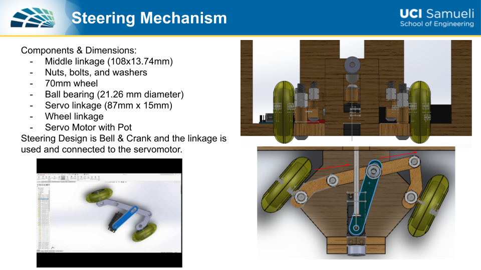
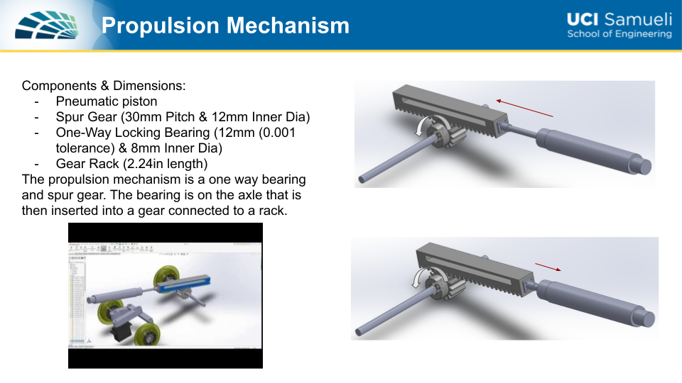
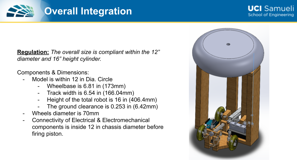
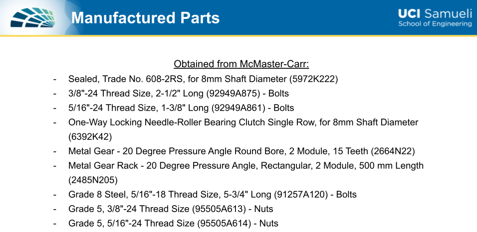
In the first part of the class, I was partnered with 3 other students to design, simulate and then present our concept of the robot. The main requirement was to position the required components within the model under the dimensions of a 16" height and 12" width, not including the piston's extension. For my team’s design, I had suggested that we keep all of the components on the base of the platform to keep the weight evenly distributed so during turns it wouldn't tip. We also made sure to get the power of the piston from the back of the robot at a low enough angle for a maximum push. After planning the rough placements for the components, the next step was to build the model using SolidWorks. In my team, I was the only one who had completed a class on how to use the program so I taught and led my other teammates on how to use SolidWorks. I was also responsible for simulating the steering and propulsion as seen below.
Following the presentation of modeling the robot, I was tasked to present 3 simulations of open-loop, closed-loop, and hybrid control types. These were run using a pre-programmed Matlab code given by my professor and I had added my parameters for my results. The last two slides were dedicated to my test on the effect, if any, the magnetometers had on closed-loop control.
Controller Design Simulation for Robot
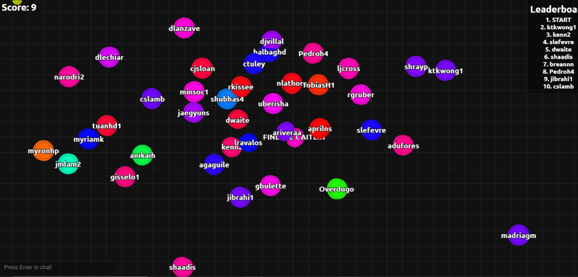
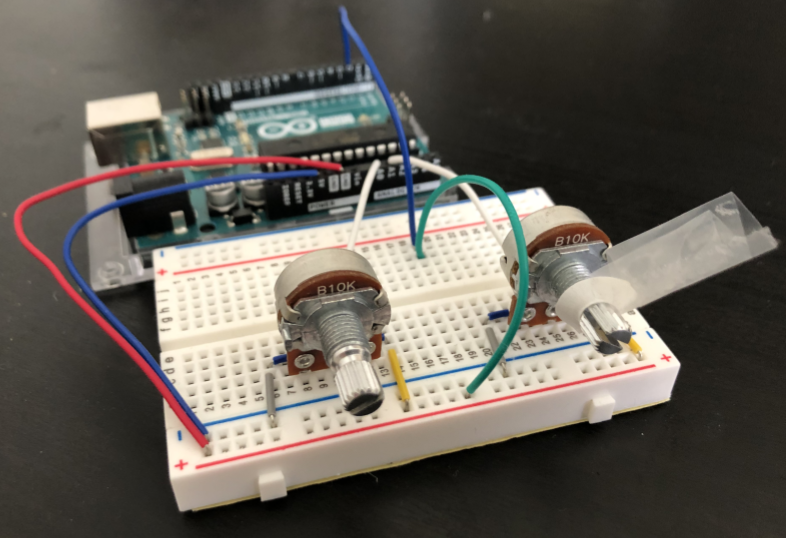
Finally, the last section of the course was dedicated to building and debugging my controller to compete against my classmates in Agar.io. Like the previous assignment, I was given a Matlab code from my professor to start circling the mouse. The next step was to code an Arduino code that connected my mouse to my controller. When creating my controller I wanted to make sure that (a) I could seamlessly change direction (b) the mouse can accommodate the starter Agar.io size as well as when I grow and (c) quickly stop and start again to evade my peers. For my final design, I had made the left potentiometer control the piston and the right potentiometer control the steering angle. I added a flag to indicate where the 0 point is on the steering angle so when I turn it left and right I can counter the angle to straighten it out when needed. This allowed me to change direction however not as seamless as I wanted as I would get stuck in a circle or not be able to turn in the opposite direction as quickly as I needed to. However, the piston potentiometer was scaled to a 0 to 1 range and as I increased the pressure to 1, the radius that my mouse took would increase and let me go faster as well as make sure my mouse can still reach the outside diameter of my Agar.io circle. This 0 to 1 range also helped me turn off and on my mouse movement and was successfully conserving the piston in the competition.