3D Printed External Elbow Fixator Prototype
The first class that I took that sparked my interest to minor in Biomedical Engineering was Engineering Analysis/Design: Computer-Aided Design that introduced me to SolidWorks and Computer-Aided Design software. Using these programs I was able to design, analyze and create a rapid prototype through manufacturing and budget planning. I was also able to share my group and I’s visualization through phased presentations throughout the quarter.
This course project was divided into a 3 phase program regarding our prototype build process but lectures were still held simultaneously continuing SolidWorks lessons. From this, I was able to efficiently divide my time to multitask both my homework assignments on the program and then replicated what I learned to finish printing the prototype.
The project was initiated during our 3rd week of the quarter. I had already researched the topic I was interested in and needed to find a group that would also like the topic. Luckily, I found a group of 3 that formed without a project topic and were keen on the idea of doing an elbow fixator that I recommended. This had set up our team to work on Phase 0 which required us to propose our topic and how we will accomplish this goal by the end of the quarter.
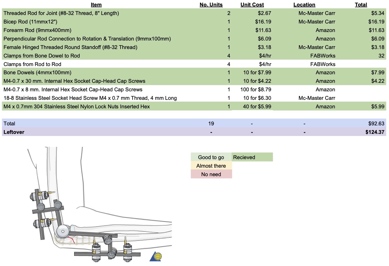
After turning in our initial design expectations, I further explored the options we had for our parts. I made a spreadsheet of possible components making sure to list their vendor, individual and bulk price and the quantity we needed of each. This helped my team to apply our real measurements to our CAD joint connectors and plan ahead while waiting for the delivery.
Phase 1 of the project was to present our project to our class. The expectations were to have some CAD planned and to share the engineering drawings of them to convey our idea of what we intended to build.
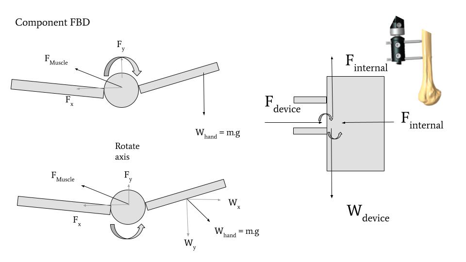
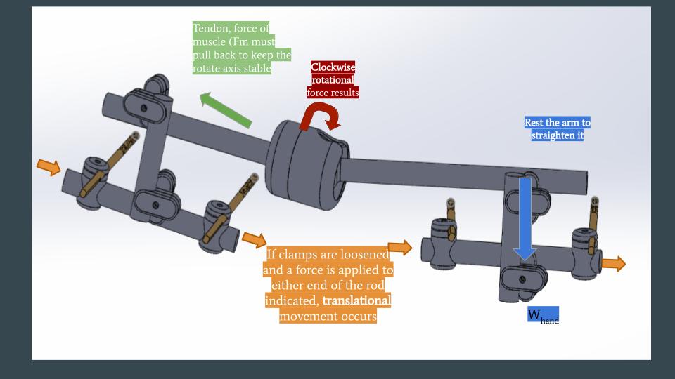
Our design also had to have a minimum of 3 ranges of motion and could be repeated as long as they are applied to a different component. Within the prototype my team and I planned to have 2 translational movements to adjust the horizontal rods attached to the pins and the vertical rod to adjust the distance of the main component. Next, rotation was used for the center of the part where the patient would bend the arm up and down.
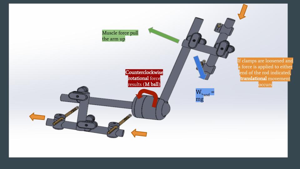
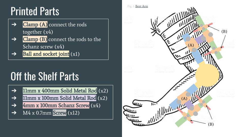
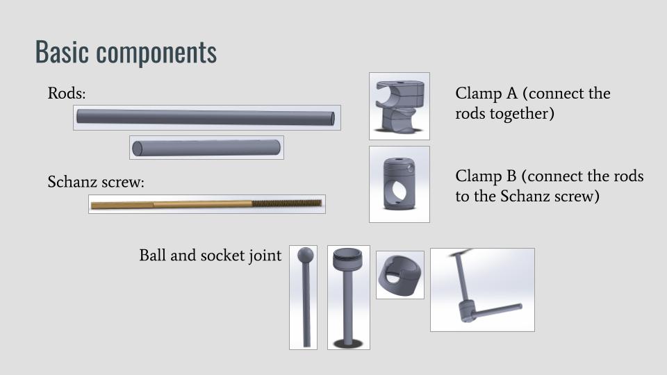
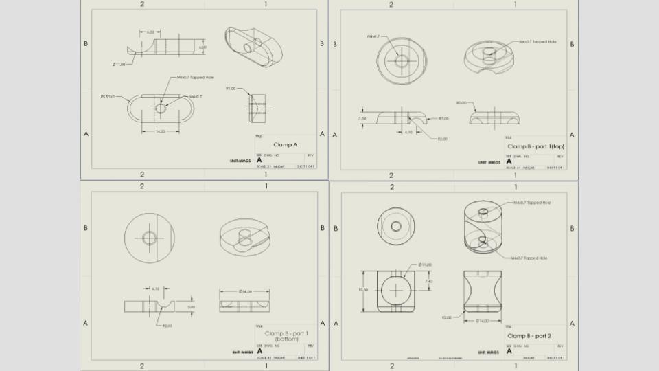
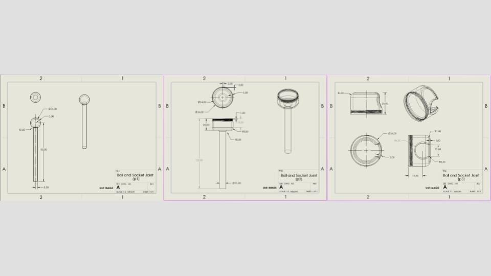
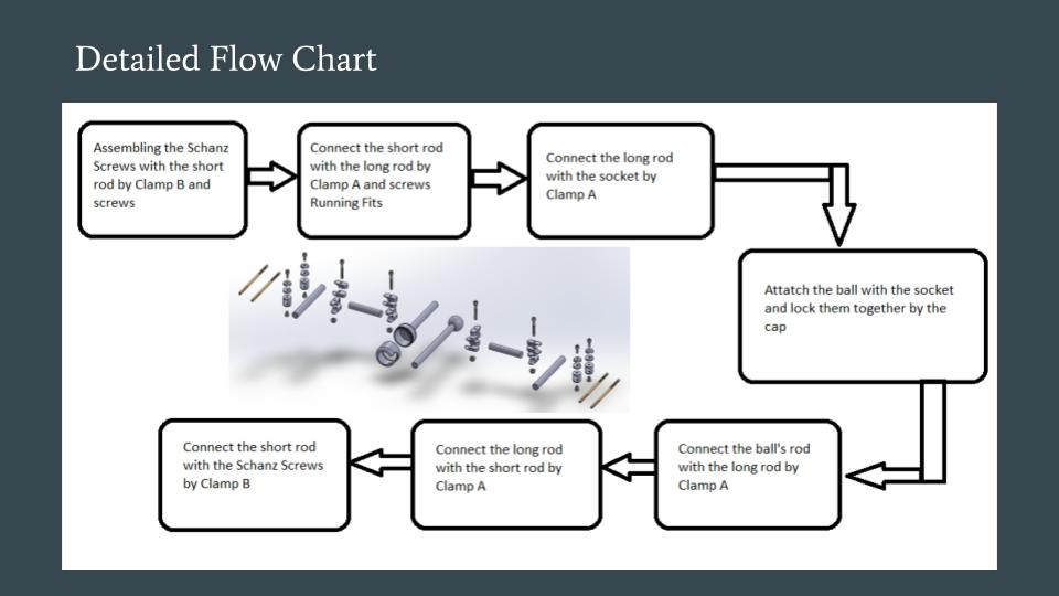
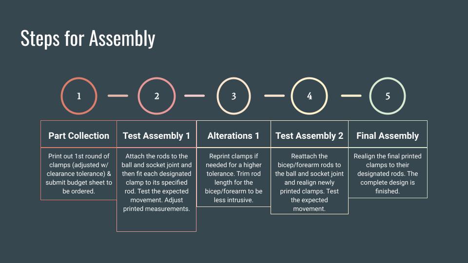
Below are the CAD files of each part and their respective engineering drawings. The entire assembly was designed in SolidWorks but our team only intended on 3D printing the clamps to attach the rods together. The entire assembly was modeled with the actual measurements of our parts to get an idea of how we will assemble the final prototype. This is also detailed in our flow chart and steps to assemble slides.
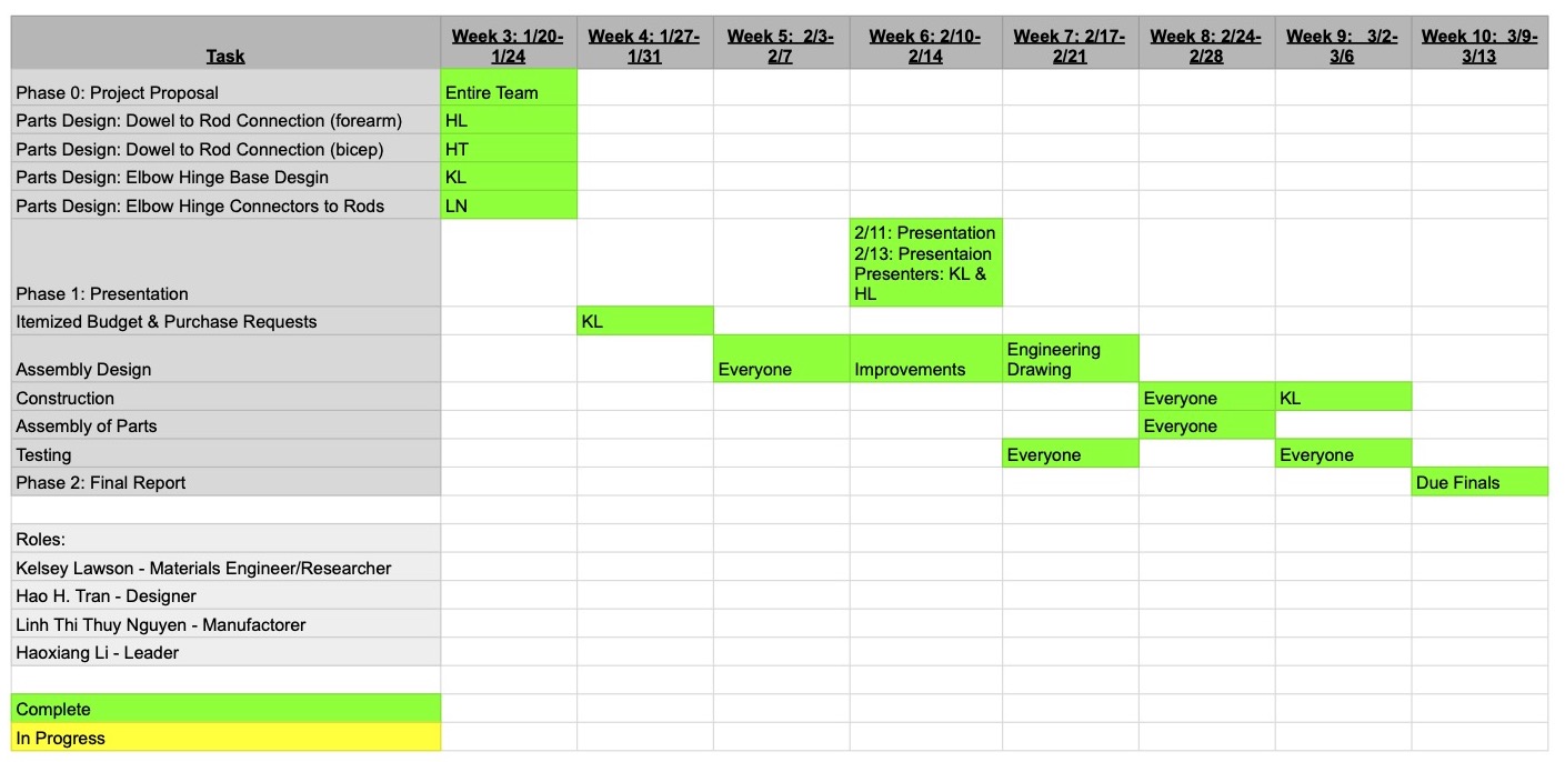
Even with the unexpected shut down of campus from COVID-19 affecting the completion of Phase 2, I made sure my team was ontrack from the beginning, filling out every task on our schedule.
Therefore, all that was left was to give our final presentation on our completed prototype which was supposed to take place during finals week. Since we couldn't be on campus, my team and I were allowed to make a video supporting our project instead of a formal presentation. I was given the chance to make our video and got the creative liberty to direct and draw our video for the assembled prototype. Alongside the presentation, in Phase 2 my team was tasked to compile our work into a final report.